
Flashing the Sonoff S31 with ESPHome
A friend of mine turned me on to Home Assistant which is a wonderful open source home automation platform. It's privacy forward (a hard requirement for me) and includes energy monitoring. It's got a neat event based system, lots of out of the box integrations and a large community of people making, hacking and helping. But what good is a home automation platform without hardware for home automations?
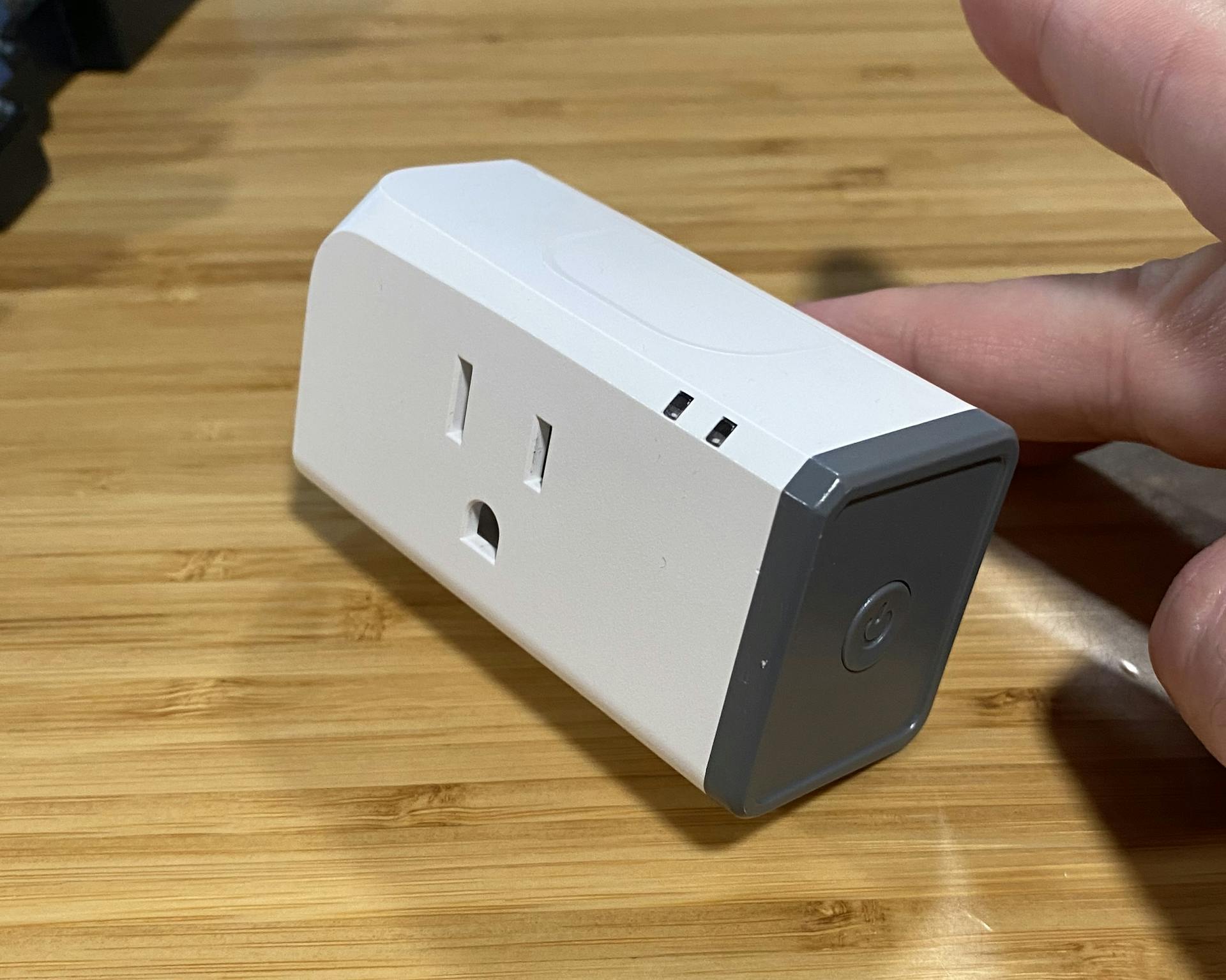
So one of the first things I got was a wifi outlet. The Sonoff s31. It includes an button, a relay, a current and voltage sensor, and an ESP based controller (Reports of an esp8266 or an esp8285). It connects to Sonoff's servers and has an app. I'm sure that's fine but lets replace it with something that works for us.
Overview
We're going to do the following;
- Take the device apart and flash it with ESPHome
- Connect it to Home Assistant
We want firmware that talks to our Home Assistant server and nobody else and ESPHome is just the ticket. It's a framework to manage many different kinds of ESP based devices and has support for many of Sonoff's devices including the S31. It's well supported and secure via the Noise Protocol which I find fascinating.
Home Assistant has a ESPHome add-on that makes it easy to manage and configure your devices. This part is nice and straightforward.
A warning about the hardware
You might notice that ESPHome shows the S31 has 3 GPIO pins in use leaving a few more unused. If you want to use them you do so at your own peril. This board is not split into high voltage and low voltage sections as a "non-isolated device". The current monitoring chip needs access to the mains which ties the digital ground to the AC neutral line, often known as "hot ground". This causes the GPIO have a high voltage differential outside of the unit so anything you attach should be considered as dangerous as a live wire. Be espicially careful of your computer, it should not be attached to the S31 when it is plugged in. It might just fry your USB/Serial adaptor but don't take the risk.
Hardware overview
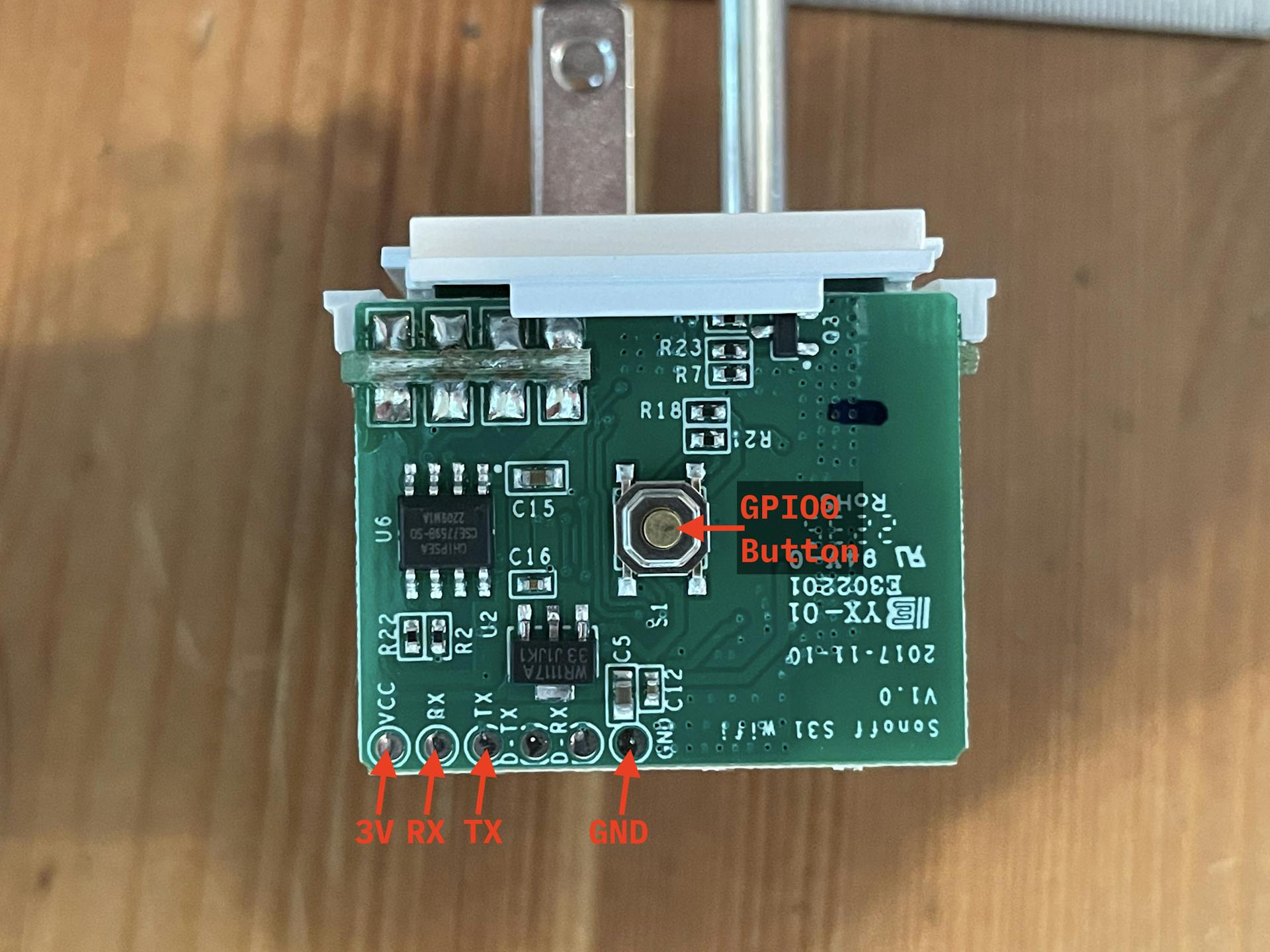
The GPIO pins that are used are;
GPIO0is the button (pulled high, reads 0 when pushed, 1 when not)GPIO12is the relay and red LEDGPIO13is the green LED (inverted logic, set to 0 to turn on, 1 to turn off)
Connected via serial UART is a cse7766 a current and voltage sensing chip (Produced by "Chipsea" but I can't find info online in english language searches) this provides current voltage, amperage and power readings.
Disassembly and Flashing
To flash ESPHome onto the device we'll need to take it apart and connect to the serial pins on the circuit board. We'll connect these pins to a USB serial adaptor and use ESPHome's web interface to flash the device.
Tools you'll need:
- Small Philips head screwdriver
- Test Hook Clips
- USB to TTL serial adaptor that runs at 3.3V (unknown if the S31 is 5v tolerant)
Dear reader, do not have your device plugged in for any part of this operation. You don't need AC power to flash the device and you don't want AC power connected to your computer.
You'll start by pulling off the button. I can use my fingers but I've used a spacer and even a wrench (with some padding) to get leverage. The button is held on by a plastic clips.
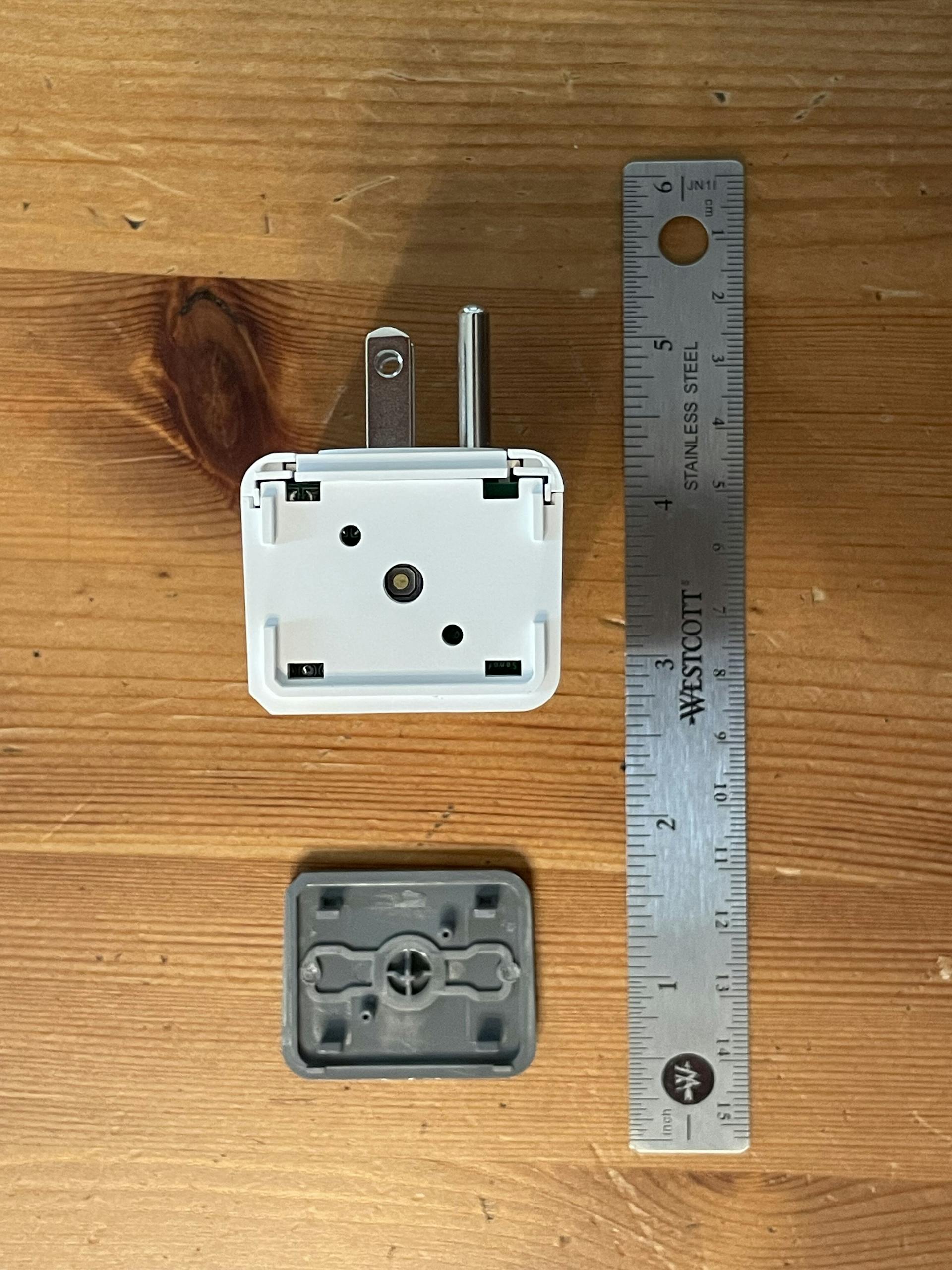
Then you then slide the corners off the device.
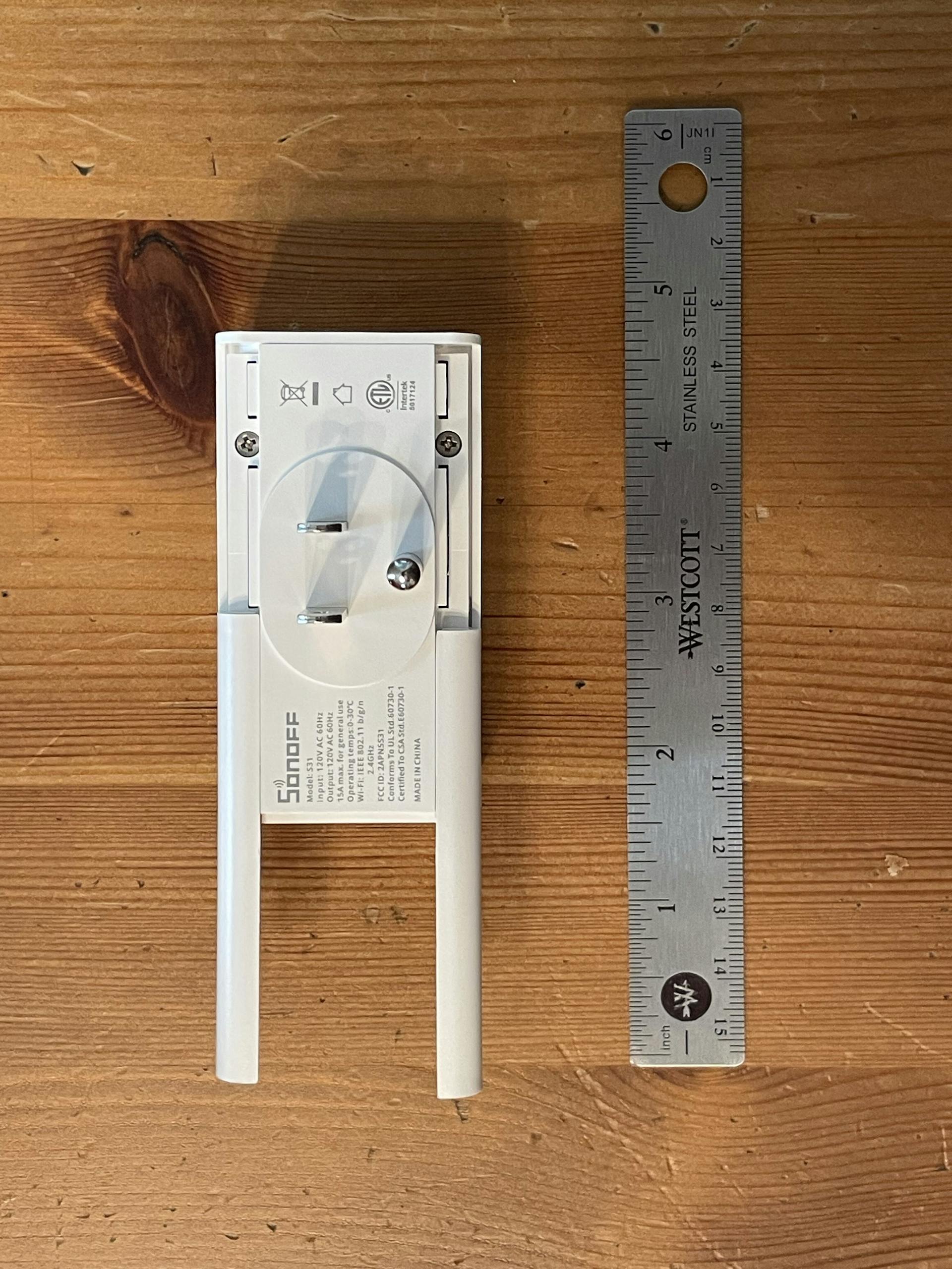
There are 3 screws to remove and then you can pull the top casing off exposing the circuit boards inside.
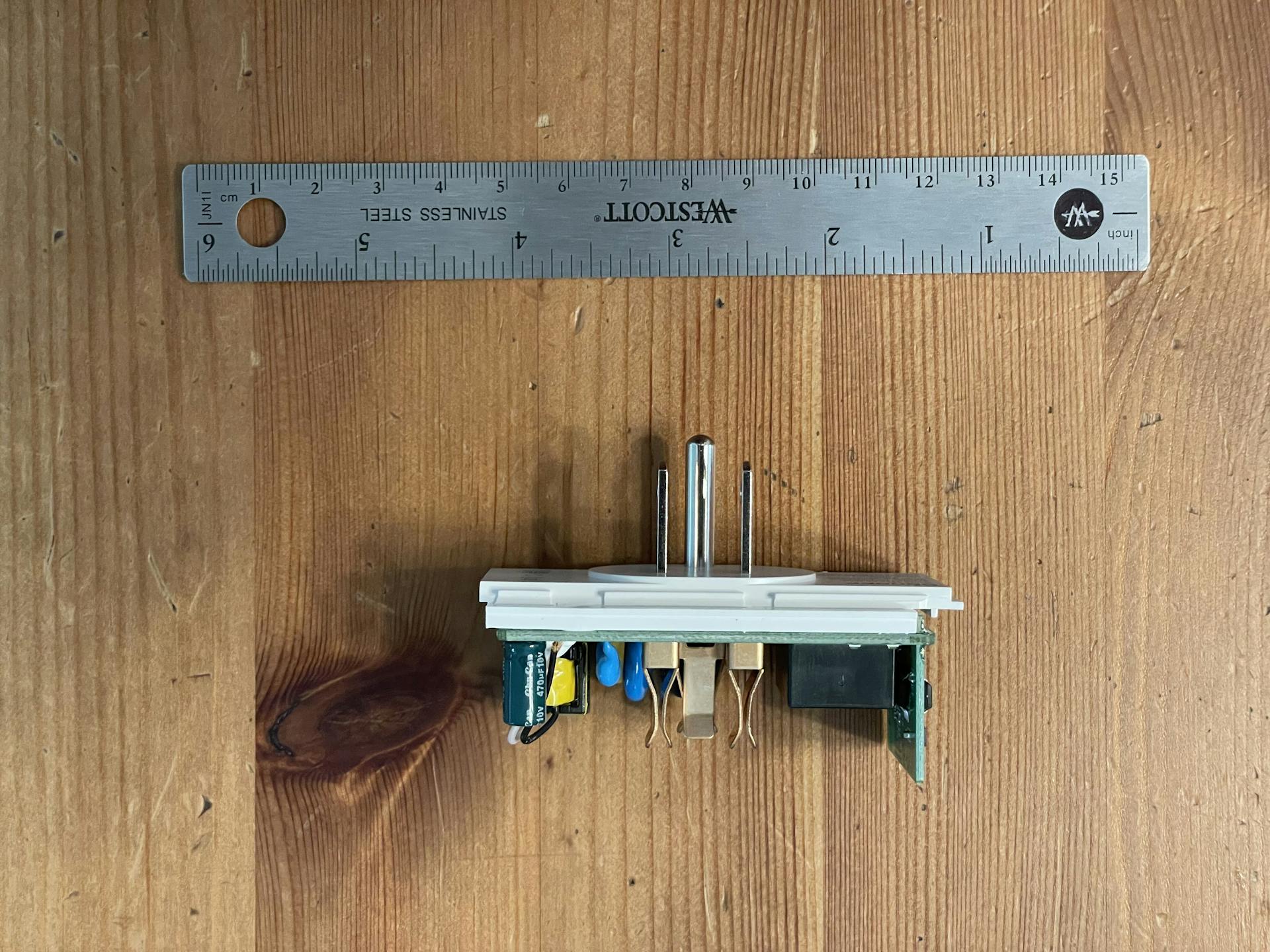
Note the pinout of the Sonoff's ESP chip.
Next you'll want to connect the USB Serial Adaptor power and Serial pins to the sonoff;
USB Serial Adaptor → Sonoff S31
- USB
GND→ S31GND - USB
TX→ S31RX - USB
RX→ S31TX - USB
3.3V→ S31VCC
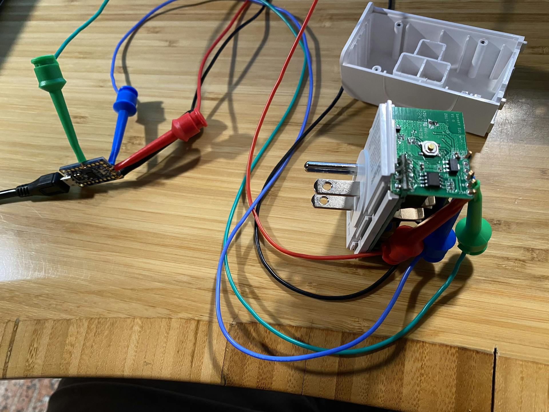
Then hold the button (which connects GPIO0 to ground) and plug in the USB Serial adaptor to your computer. This will boot your device into flash mode. Once you see the blue light blink you can release the button. You can now flash the device with ESPHome.
The easiest way to do this is to navigate to https://web.esphome.io/ with google chrome or chromium or any browser with WebSerial support.
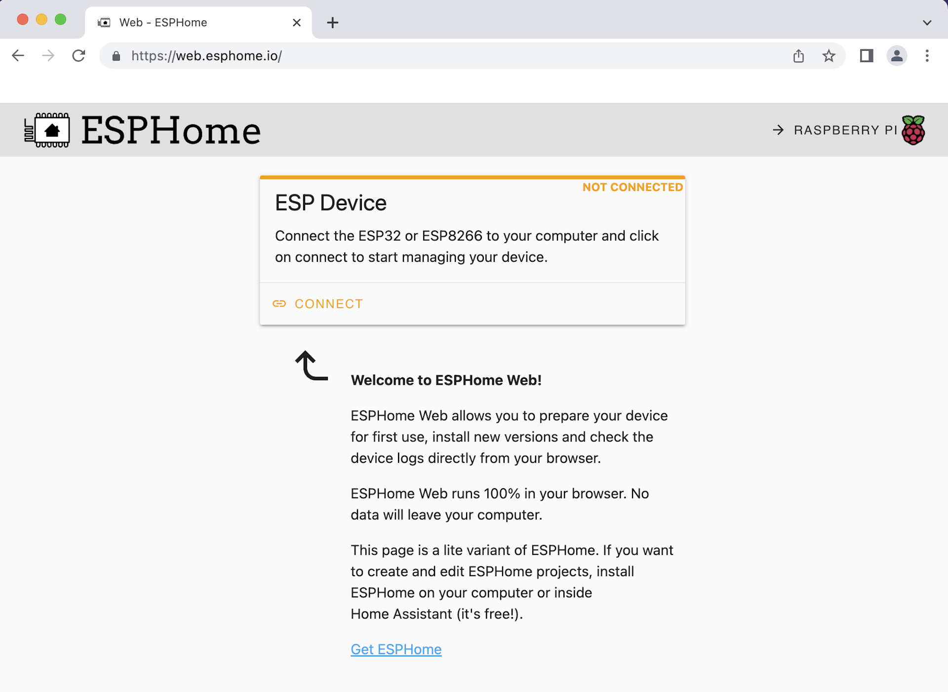
You'll need to select the USB device of your Serial Adaptor and let it flash your device. After flashing you need to reboot your S31 by unplugging it and plugging it back in. Then you can connect to it again and set your wifi credentials.
If it can't connect to your wifi it will boot into AP mode and broadcast it's own SSID. It is possible to connect to that and set WIFI credentials too.
Once it's on your network you can add it to Home Assistant.
Setup Home Assistant and Load Settings
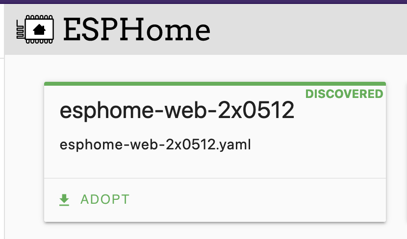
To use the device you'll need to install the Home Assistant ESPHome Add-on which is straightforward. Then you will see a new ESPHome section in the sidebar.
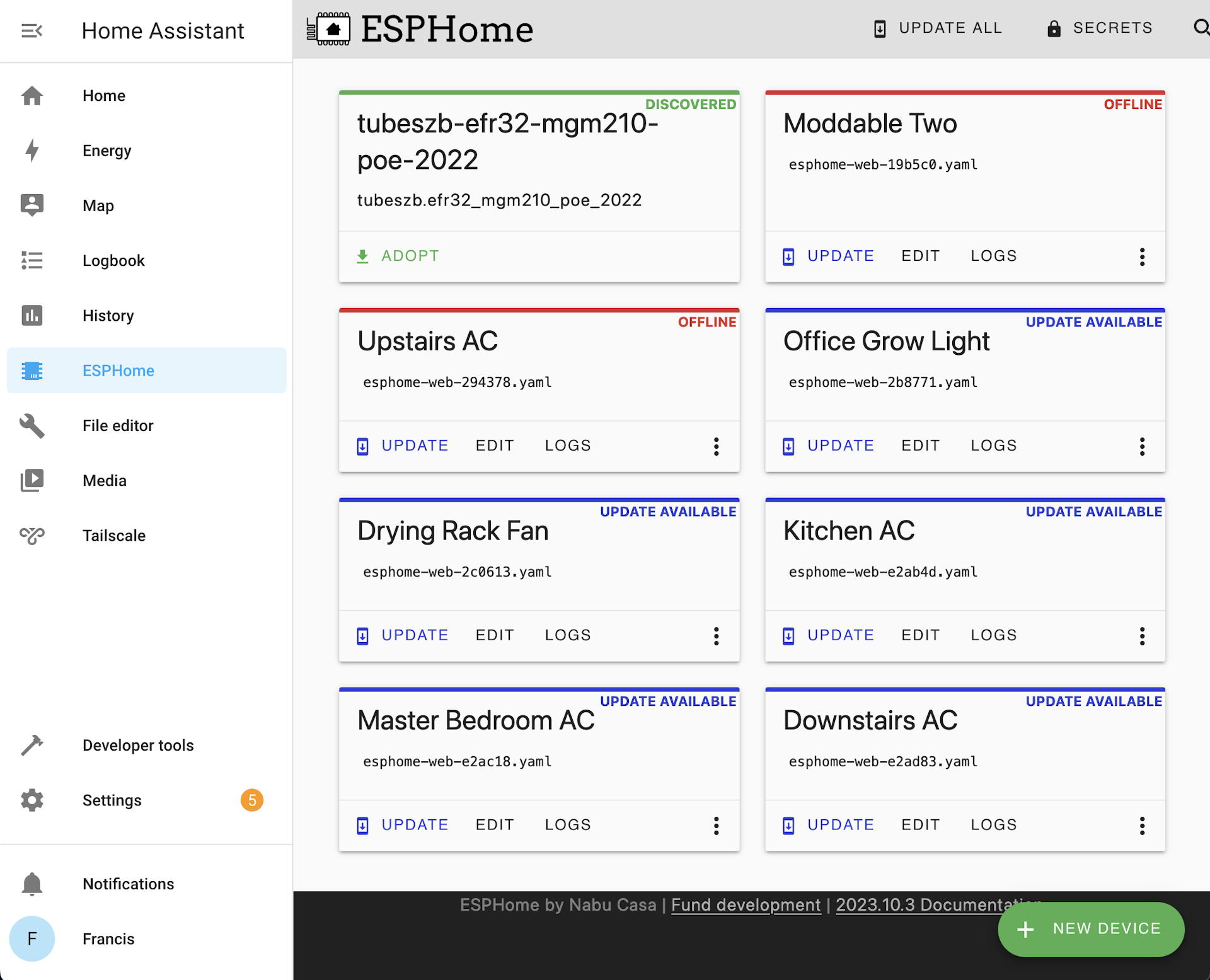
Then you should see your device appear for adoption. Click adopt and let it setup the device.
Once adopted you'll need to add a configuration for the S31's hardware. You can use the following to add to the default configuration; Make sure to modify your existing logger section.
# Disable logging
logger:
  baud_rate: 0 # (UART logging interferes with cse7766)

wifi:
  ssid: !secret wifi_ssid
  password: !secret wifi_password

  # Enable fallback hotspot (captive portal) in case wifi connection fails, use your own ssid/password here
  ap:
    ssid: "Esphome-Web-XXXX"
    password: "XXXXXX"

captive_portal:

uart:
  rx_pin: RX
  baud_rate: 4800

binary_sensor:
  - platform: gpio
    pin:
      number: GPIO0
      mode: INPUT_PULLUP
      inverted: True
    name: "button"
    on_press:
      # Ensure the switch always operates the relay
      - switch.toggle: relay
  - platform: status
    name: "status"

sensor:
  - platform: wifi_signal
    name: "wifi_signal"
    update_interval: 60s
  - platform: cse7766
    current:
      name: "current"
      accuracy_decimals: 1
    voltage:
      name: "voltage"
      accuracy_decimals: 1
    power:
      name: "power"
      accuracy_decimals: 1
      id: power
  - platform: integration
    name: "energy"
    sensor: power
    time_unit: h
    state_class: measurement
    unit_of_measurement: kWh
    filters:
      - multiply: 0.001
  - platform: total_daily_energy
    name: "Total Daily Energy"
    power_id: power

time:
  - platform: sntp
    id: the_time

switch:
  - platform: gpio
    name: "relay"
    pin: GPIO12
    id: relay
    restore_mode: ALWAYS_OFF # Modify this as it makes sense for your use case

status_led:
  pin: GPIO13
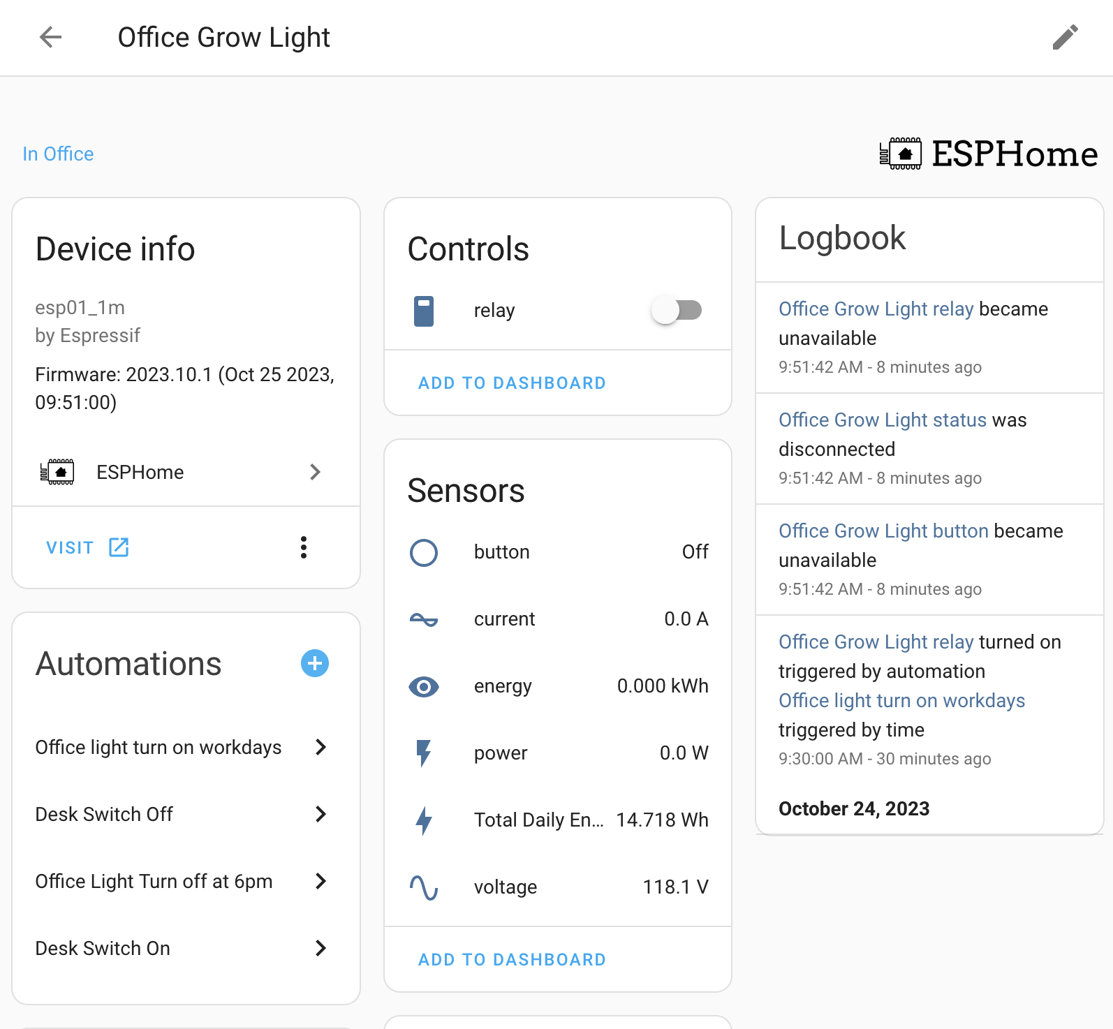
Click Save and then Install watch the firmware compile and load over the air to your plug. You can now put it back together and plug it in. In Home Assistant you should see the device appear and you can add it to your dashboard and setup automations. I use this device control a large light in my office. It turns on in the morning and off and the end of the work day but only on workdays. Additionally I have a switch that I can use to turn it on and off manually.
Todo
No project is left without a healthy list of todos. Mine is just one, get this working better with the Home Assistant Energy Dashboard. The Total Daily Energy sensor works but it would be nice to have near realtime data.
References
Powered by ⚡️ and 🤖.